Tilting Maze Final Project Document
Introduction
Tilting Maze is a course final project for 16-223 Creative Kinetic Systems at Carnegie Mellon University. My teammate for this project is Xueting Li. You can find project information and some short demo videos in this post.
Abstract
The tilting maze is a collaborative ball maze game where each player controls one rotation axis. The goal of the game is to follow the designated path and collect all the stars along the way. This game is designed to inspire a sense of cooperation between young players and bring them moments of delight by giving reward feedbacks. From our observations, the game did achieve our goal.
Objectives
- The maze board of the machine should be able to perform independent rotational motions in two axes: roll and pitch. The magnitude and rate of the response should be maintained at a suitable level so that the ball can be controlled at users’ will.
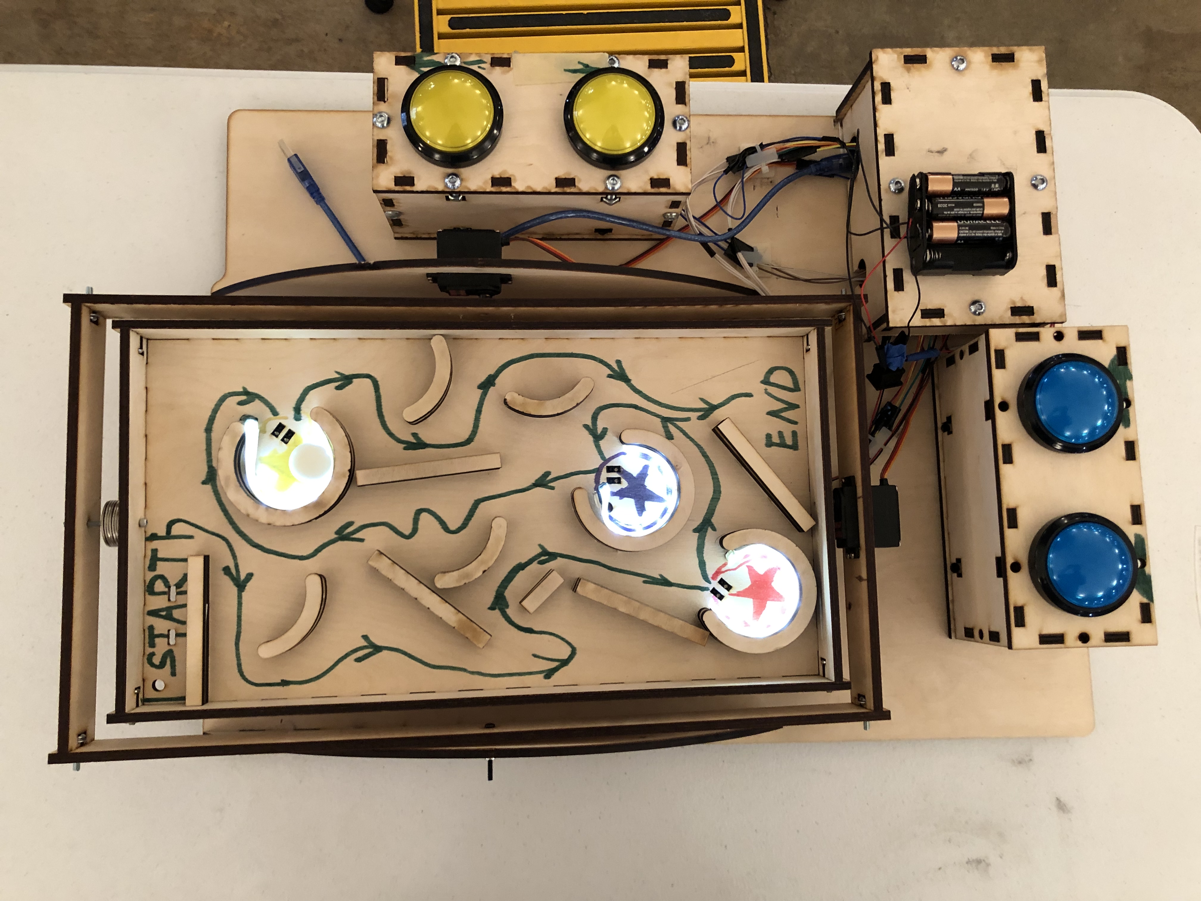
- The maze should be arranged such that there exist obvious start, end, bonus positions, and paths. The ball should be able to move around the maze without stuck anywhere.
- The control method should be obvious and intuitive, encouraging children to manipulate the machine with designated controls and use them in the right way.
- The device should have strong and obvious feedback to the users when they achieved certain goals.
- Overall, the game should encourage players to work together and inspire their senses of cooperation.
Implementation and Design Choices
Mechanical and Mechanism
- The main chassis, maze board, controller stations, and wiring shield are made from 6mm plywood. The main fabrication method for the parts above is laser cutting. We choose plywood as our main material because it is relatively lightweight compared with metal, and easy to manufacture with a laser cutter. Plywood is also the material with the easiest access for us.
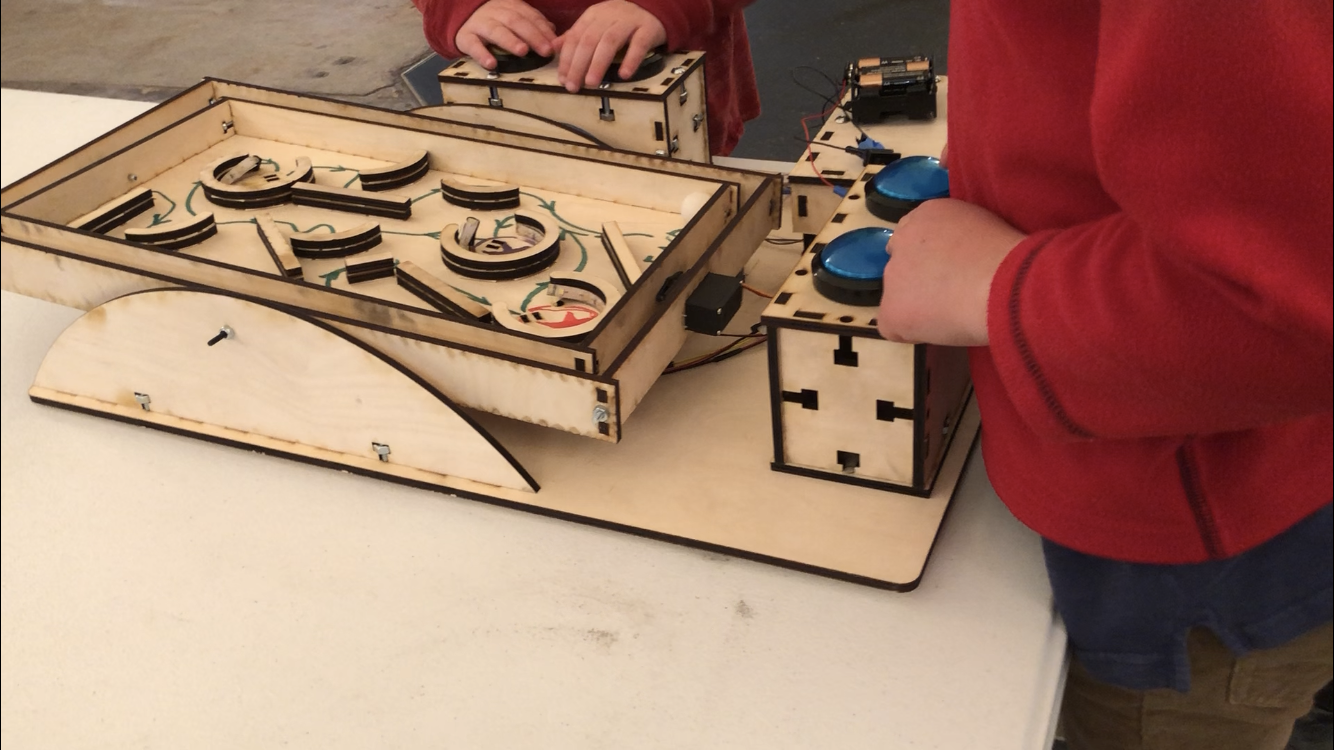
- The rotation mechanism is achieved by implementing a 2-axis gimbal, with two hobby servos each controlling one axis of motion. Considering the small inertia of the rotating frame, and to reduce complexity and increase maintainability of the device, we attached the rotating frame directly to the servo motor, without any gearing.
- We use M4 bolts and lock nuts for the support of the rotation axes. We chose not to use bearings because of the small mass of the system.
- Captive screws mechanism is used to secure connections between vertically mating faces.
- Arcade push buttons are used as the control interface and are located at each corresponding control axis.
- A wood wiring shield box is placed on top of the breadboard to protect the circuits.
- Maze components (straight bars, circles, etc) are made from plywood and laser cutting. They are then arranged and put on the maze board with double-sided tape. Example paths and star bonuses are drawn in different and vibrant colors.
Electrical
- Proximity sensors are placed at the entrance of each bonus location (the star) to detect if the ball gets there. The proximity sensors are then connected to the analog pins of the Arduino.
- LED arrays are placed at the walls of each bonus location (the star). The positive and ground are then connected to the collector and the emitter of a transistor respectively, which are then connected to the 9V and ground bus. The Vin of the transistor is connected to a digital out pin of the Arduino.
- Arcade switches are connected into the circuit such that when the switch is closed, the Arduino analog pin will read high and read low otherwise. 1K pull-up resistors are used in the circuit.
- A speaker is connected directly to the Arduino 5V digital output.
- A pack of six 1.5 volts AA batteries is used as the power source of the device.
Software
- To avoid using delay() function, time elapsed is calculated after each loop. Other functions may take in time elapsed to keep track of duration.
- A threshold of 100 is set on the proximity sensor reading. A reading below the threshold will trigger corresponding LED strip and pre-defined reward tone from the speaker.
- A “pitches.h” header file is included to the main file. The header file includes macros for Arduino analog output value to corresponding pitch. It is used in the definition of the reward tone.
- An auto-move mode is implemented. The auto-move mode is a set of predefined control inputs that are automatically performed by the device when no user plays it for 40 seconds. The auto-move mode terminates once either of the control axes receives input from a user. This feature is designed to attract potential players when no one has played it for a while.
- A keystroke delay of 80 ms is implemented. This feature is designed to guide young players perform meaningful control, instead of rapid random keystrokes.
Outcomes
Functional Outcomes
- The servo motors provide enough torque to drive the gimbal frames, providing independent and responsive motions. Objective 1 is met.
- The maze is arranged reasonably and the color plays a significant rule for players to define their objectives (spot the stars, follow the lines, etc). Objective 2 is met.
- Proximity sensor, LED, speaker and other electronics function without exception throughout the entire visit session of two hours. The pack of six 1.5 volts AA battery lasts the entire session.
Non-functional Outcomes
- The arcade buttons attract players from all ages. The players can easily grasp the controlling intention of the buttons and start playing the game by pressing them intuitively. The keystroke delay achieved nominal control guidance from our observation of different actions of children from first and second Children’s Museum visits. Objective 3 is met.
- The players can easily feel the sense of achievement when they see the LED of the stars lit up and hear the reward tone from the speakers. The user feedback from the device is obvious and easy to get. Objective 4 is met.
- From our observation, the separation of the control buttons guide the users to collaborate with each other and encourage communication between players. Pairs with mutual goal and collaboration usually result in better gaming experiences, which also helped other players to realize the cooperation component of the game. Objective 5 is met.
Surprising Outcomes
- We observed that when the two players could not collaborate accordingly, an instructor can help them work together effectively. Usually, the instructor is the parent of the children. Either the parent plays as the teammate of the child or guides two children play with each other, the instructor’s presence enhances the gaming experience significantly.
- We also observed that some children modified the rule of the game but still enjoys it. Though in this case, the game did not meet its objectives, it at least brings laughs to the player, and we are still happy with this outcome.
Contribution
Henry Zhang: Electronics; Aruidno programming; mechanical design and manufacturing of the button housing.
Xueting Li: Mechanical design and manufacturing of the chassis, gimbal frame, and wiring housing; wire fabrication.
Supporting Media
Videos
Images